
Motivation
Fifth Generation (5G) cellular systems are being designed to communicate over both sub-6 GHz bands (a.k.a. Frequency Range 1) as well as mmWave bands (a.k.a. Frequency Range 2). mmWave spectrum offers abundant bandwidth, which can be used to support multi-Gbps transmission speeds per user. Historically, mmWave bands have been used for fixed/mobile satellite services (FSS/MSS) and local multipoint distribution service (LMDS). Recently, the Federal Communications Commission (FCC) has opened up nearly 11 GHz of the mmWave spectrum for mobile broadband, aiming to support 5G cellular systems, wireless LANs (e.g., Wi-Gig), and others. The newly allocated bands include licensed bands at 24 GHz (24.25-24.45 GHz and 24.75-25.25 GHz), 28 GHz (27.5-28.35 GHz), 37 GHz (37-38.6 GHz), and 39 GHz (38.6-40 GHz), as well as a new unlicensed band at 64-71 GHz – see Figure 1. Combined with the previously introduced 57-64 GHz unlicensed band, this creates almost 18 GHz of new spectrum for next-generation wireless systems. The FCC is also planning to add 15.8 GHz more spectrum at 31.8-33.4 GHz, 42-42.5 GHz, 47.2-50.2 GHz, 71-76 GHz, and 81-86 GHz bands, along with spectrum above 95 GHz.
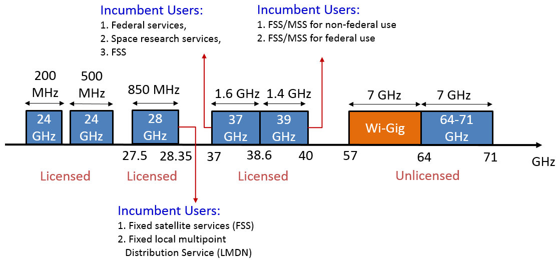
Figure 1: Licensed and unlicensed bands in the mmWave spectrum.
Despite this abundant capacity, RF communications at mmWave frequencies can be quite challenging, due to high propagation losses, poor penetration, blockage, rain sensitivity, etc. At the same time, the smaller wavelengths make it possible to pack tens or even hundreds of antenna elements into a single device (mobile phone, Small base station, or access point). With proper processing of signals fed into these antennas, electronically steerable, highly directional transmissions can be performed. The severe signal attenuation can, thus, be compensated for by the resulting beamforming and spatial reuse gains.
There are several ways to apply beamforming at mmWave frequencies. Fully digital beamforming relies on the availability of several RF chains. A particular precoding vector is multiplied by the modulated baseband signal of a given RF chain. Analog beamforming, on the other hand, can be performed with a single RF chain. It applies the beamforming weights in the RF domain by controlling phase shifters. Finally, in hybrid (analog/digital) beamforming, the signal processing is divided between the analog and digital domains, allowing comparable performance to digital beamforming but with fewer RF chains. The low power consumption of the analog beamforming makes it a desirable architecture, especially for the user equipment (UE).
Our effort addresses the challenges of directional communications at mmWave frequencies, with applications in 5G cellular systems, WiGig, drone communications, intelligent transportation and connected vehicles, and others. Specifically, our research agenda focuses on the following themes:
- Fast Network Discovery and Tracking for 5G mmWave Cellular Systems
- Optimization and User-dependent Adaptation of Beamwidth
- Blockage-resilient Directional Communications
- mmWave Channel Characterization
- Sharing and Dynamic Allocation of mmWave Spectrum
Related Publications:
- Irmak Aykin, Berk Akgun, Mingjie Feng, and Marwan Krunz, "MAMBA: A multi-armed bandit framework for beam tracking in millimeter-wave systems," accepted to appear in the Proc. of the IEEE INFOCOM 2020, Beijing, China, April 2020.
- Irmak Aykin, Berk Akgun, and Marwan Krunz, "Multi-beam transmissions for blockage resilience and reliability in millimeter-wave systems," accepted to appear in IEEE Journal on Selected Areas in Communications (JSAC) - Special Issue on Millimeter-wave Networking.
- Berk Akgun, Marwan Krunz, and David Manzi, "Impact of beamforming on delay spread in wideband millimeter-wave systems," accepted to appear in the Proc. of the IEEE ICNC 2020 Conference, Big Island, Hawaii, Feb. 2020.
- Irmak Aykin, Berk Akgun, and Marwan Krunz, "Smartlink: exploiting channel clustering effects for reliable millimeter wave communications," Proc. of the IEEE INFOCOM 2019 Conference, Paris, France, Apr. 2019, pp. 1117-1125.
- Irmak Aykin, Berk Akgun, and Marwan Krunz, "A Method for Fast Beam Sweeping and Device Discovery in 5G Millimeter Wave and Upper Centimeter Wave Systems," Application No. US 62/742,206, Filing Date Oct. 5 2018.
- Irmak Aykin and Marwan Krunz, "FastLink: An efficient initial access protocol for millimeter wave systems,” Proc. of the ACM International Conference on Modeling, Analysis and Simulation of Wireless and Mobile Systems (MSWiM 2018), Montreal, Canada, Oct. 2018, pp. 109-117 (received best-paper award).
Fast Network Discovery and Tracking in 5G mmWave Systems
In 5G New Radio (NR), the base station (BS) needs to discover devices that enter its range and track them as they move around. This initial access and network discovery process (a.k.a. cell discovery) must be performed within a strict time interval (e.g., 5 milliseconds). The strict constraint on discovery time can be challenging under high and unpredictable mobility. Tracking already discovered devices is yet another challenge, especially when sudden changes in the environment disrupt the ongoing communications. Even at pedestrian speeds, frequent beam misalignments can occur. At higher speeds (e.g., drone communications, connected vehicles), beam misalignment can lead to severe outcomes. In current, sub-6 GHz LTE systems, initial access is performed in an omnidirectional fashion, and directional transmissions may take place after a physical link has been established, typically via digital beamforming. For mmWave systems, such an approach is inefficient, as it would result in very limited range for the discovery messages.
Beam Finding
To find a suitable directional link, recent 5G specifications require that the BS to periodically broadcast synchronization signal (SS) blocks along predefined beam directions in a sequential manner (see Figure 2). With this sequential search, initial access (IA) and association can be particularly challenging, considering the time required for the BS and user equipment (UE) to align their beams properly. Existing approaches for IA in directional networks include exhaustive search, iterative search, and context-information-based search. These approaches suffer from either long discovery time or high misdetection probability of new UEs. In this thrust, we are exploring novel time-efficient IA protocols for mmWave systems based on electronically steerable antennas.
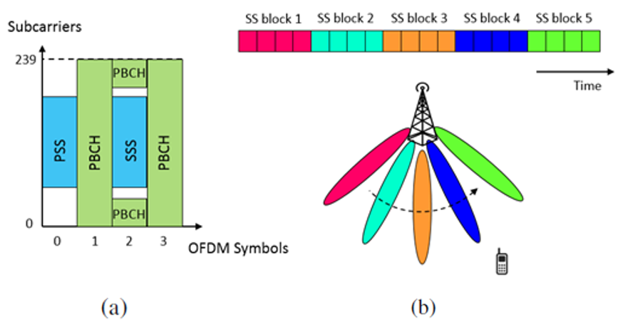
Figure 2: 5G NR initial access. (a) SS block structure, (b) beam sweeping procedure shown in spatial & time domains.
One example of our previously designed protocols is called FastLink. In this protocol, a device (e.g., BS) always transmits/receives using the narrowest feasible beam, allowing for a high beamforming gain and a low misdetection rate. To determine the required number of scanned directions, we formulated the beam-finding process as a sparse problem, exploiting the poor scattering nature of mmWave channels. We used compressive sensing to determine the minimum number of measurements needed to reconstruct the sparse channel. We then integrated a unique binary-search-based algorithm, called 3DPF, into FastLink so that it scans only a small subset of the angular space and finds in logarithmic time the best transmit-receive beam combination for a given UE. 3DPF divides the set of beam directions into equally spaced subsets, where each subset is guaranteed with high probability to contain a single channel cluster, and then finds the beam that achieves the maximum received power in that subset. The number of subsets (K) is a parameter that we determine using compressive sensing.
For performance evaluation purposes, we conducted both simulations as well as hardware experiments. Our simulations are based on the NYU mmWave channel model. Figure 3 shows simulation results of the 3DPF algorithm for different values of K, compared with ‘exhaustive search’, which is the standard beam finding approach used in the IEEE 802.11ad systems (refinement stage) and in 5G NR. By reducing the fraction of directions that need to be scanned, 3DPF is shown to significantly reduce the IA time, while maintaining almost the same misdetection probability as the exhaustive search approach.
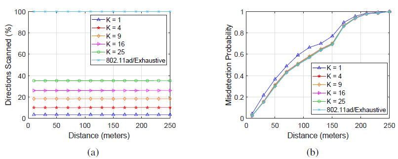
Figure 3: Simulation-based comparison between 3DPF and 802.11ad search, with 5-degree scan resolution: (a) Percentage of scanned directions vs. distance, (b) misdetection probability vs. distance.
To further verify the efficiency of our design, we conducted extensive experiments using 4x4 uniform planar arrays at both the transmit and receive sides. Keysight E8257D-ATO-8384 PSG signal generator was used to generate the signal. At the receiver side, the array was connected to Keysight PXA-550-MY55002004 vector signal analyzer (VSA). The PSG and the VSA were connected to a host PC, and the RSS results were obtained via a TCP connection. To steer the transmit/receive beams to desired directions, antenna arrays were connected to microcontrollers, interfaced with the host PC through serial port. Figure 4 below shows an example setup.
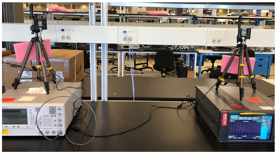
Figure 4: Example of the mmWave test setup used in our experiments (4x4 uniform planar arrays at both Tx and Rx).
Our experimental results are, generally, in line with the simulation results. Specifically, Figure 5 shows that 3DPF can reduce the search time by 50%−99% compared to the exhaustive scheme.
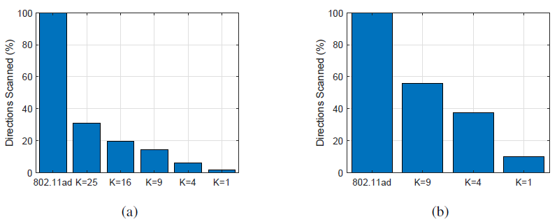
Figure 5: Experimental comparison of the 3DPF algorithm using different K values and 802.11ad/exhaustive beam scan. (a) Percentage of scanned beams for 5o sweep resolution, (b) percentage of scanned beams for 15o sweep resolution.
Our ongoing research related to beam finding and initial access is focusing on:
- Extending FastLink into a multi-user scenario
- FastLink-based design under hybrid (analog/digital) beamforming
- Hardware implementations
- Performance analysis under mobility
Beam Tracking and MCS Selection via Reinforcement Learning
In this thrust, we explore the use of machine learning methods for beam management. By adopting an intelligent tracking method, the link between the BS and the UE can be maintained even when the UE and/or BS is mobile. To achieve this purpose, we are pursuing several lines of investigation. In one approach, discussed below, we use a restless multi-armed bandit (MAB) framework for beam tracking and waveform adaptation. According to our proposed framework, each beam is modeled as an arm of the multi-armed bandit. The BS acts as the agent, interacting with these arms to learn the underlying system dynamics, i.e., changes in beam qualities over time. To quantify the quality of a beam, we consider the highest modulation and coding scheme (MCS) that can be supported by that beam. We then develop an online reinforcement learning algorithm, called Adaptive Thompson Sampling (ATS), to be used within the proposed framework for determining the optimal beam/MCS pair for each downlink transmission. ATS aims at maximizing the expected transmission rate, considering the estimated reward distributions associated with each beam. However, due to the time-varying nature of the environment (e.g., caused by UE mobility and/or environmental changes), keeping track of these reward distributions is nontrivial. To address this nonstationarity, ATS starts with prior beam-quality information, collected through the initial access process, and updates this information whenever an ACK/NACK feedback, i.e., a reward is obtained from the UE (see Figure 6). We also introduce a forgetting factor that discounts the information obtained in the past as well as a boost factor that increases the weight of recent observations on beam selection. The beam ID and MCS index to be used during the next downlink transmission are then selected based on the updated posterior distributions (see the example in Figure 7).
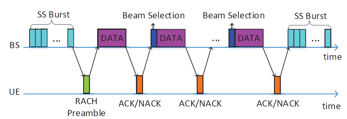
Figure 6: Timeline of the proposed downlink communication scheme between a BS and a UE.
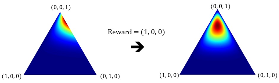
Figure 7: Example prior (left) and posterior (right) distribution heatmaps, where red denotes higher probabilities and blue denotes lower probabilities.
Due to its model-free nature, our algorithm can accurately estimate the best beam/rate pair, without making assumptions about the channel and/or user mobility. Through rigorous analysis, we show that ATS achieves very low Bayesian regret. We also derive an upper bound on this regret using discrete-time random walk processes. We have conducted extensive simulations and experiments over the 28 GHz band using phased antenna arrays to validate the efficiency of our algorithm. Our results (exemplified in Figure 8) show that the ATS algorithm improves link throughput by up to 182%, compared to the beam management scheme proposed for 5G NR (indicated as ‘Static Oracle’ in the figure). For low UE speeds, ATS is shown to perform significantly close to the ‘Dynamic Oracle’ scheme, in which beam and MCS selection is performed under exact and instantaneous channel state information.
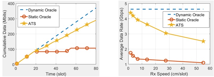
Figure 8: Performance evaluation results. (left) Cumulative data vs. time for an outdoor scenario, (right) average data rate vs. UE speed.
Our ongoing research is focusing on:
- Adapting the design parameters of the reinforcement learning algorithm based on observable system information.
- Exploiting contextual information, such as position and speed, for beam tracking and MCS selection.
- Exploring the problem of beam tracking and MCS selection for highly mobile scenarios, such as drone communications.
- Investigating cooperative beam tracking for multi-homed UEs, e.g., Coordinated Multi-Point (CoMP), where multiple neighboring BS’s coordinate their beam tracking processes.
Beamwidth Optimization and Adaptation
Intuitively, the initial access (IA) delay can be lowered by using wider beams, as fewer directions need to be swept. However, this results in a weak received signal and higher misdetection probability, which in turn increases the IA delay, as more rounds of beam sweeping will be required to discover a UE. Figure 7 described the impact of beamwidth on the beam sweeping delay. In NR mmWave cellular networks, the optimal beamwidths at the BS and the UE can be adapted, depending on the channel gain. As shown in Figure 8, when the channel gain between the UE and the BS is relatively large (e.g., BS-UE distance is small), the misdetection probability is low. In this case, the UE can employ wider beams with small antenna gains to reduce the beam sweeping overhead. Conversely, when the channel gain is small, narrower beams should be used to improve the reliability of SS detection and prevent the need to execute too many beam sweeping rounds before discovery is completed. From the perspective of the BS, beamwidth selection impacts the delays of all UEs that are trying to connect to the BS. Thus, the beamwidth at the BS needs to be optimized based on the channel gains of all UEs. In this thrust, we investigate beamwidth optimization frameworks for both standalone (SA) and non-standalone (NSA) 5G NR mmWave cellular networks. Our first aim is to determine the optimal beamwidths at the BS and the UE that minimize the beam sweeping delay for a successful IA process. To do that, we first formulate the beamwidth optimization problem by analyzing the interplay between beamwidth, beam sweeping overhead, and misdetection probability. Then, we design beam sweeping protocols that enable adaptive beamwidth configuration under NR standards. For both SA and NSA systems, we propose solutions to obtain the optimal beamwidths at the BS and the UE. Through extensive simulations, we verify the efficiency of our algorithms and show that they can significantly reduce the IA delay compared to a fixed beamwidth scheme.
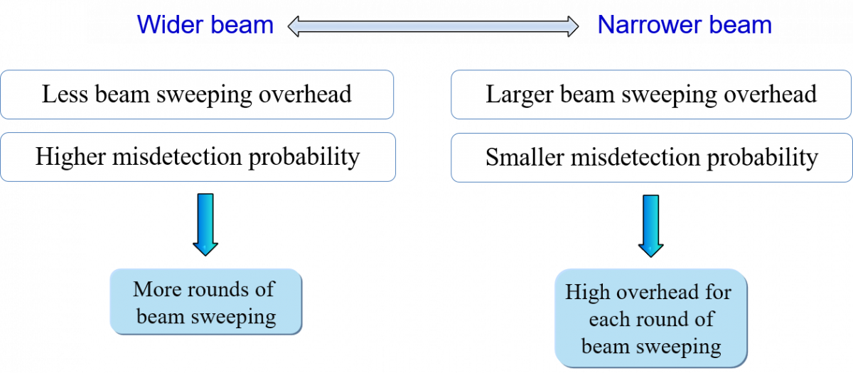
Figure 7: Impact of beamwidth on the beam sweeping delay
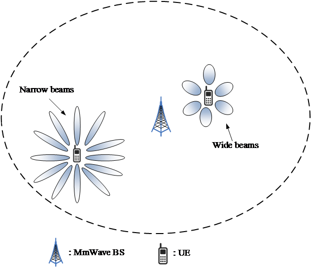
Figure 8: Adaptation and optimization of UE beamwidth in NR mmW cellular networks
Other ongoing aspects of this thrust include:
- Adapting the beamwidth for each UE, based on its behavior (speed, location, etc.)
- Investigating the interplay between beamwidth and inter-cell interference, and how it impacts the IA delay in dense cellular networks
- Extending the analysis to the scenario of digital/hybrid beamforming, which enables transmit/receive in multiple directions simultaneously
Blockage-resilient Protocols
mmWave signals are particularly prone to blockages due to walls, windows, and even human body. In this thrust, we are developing blockage-resilient communication protocols for 5G systems. One example of our protocols is called SmartLink, which exploits the clustering phenomenon at mmWave frequencies (see Figure 9(a)) to establish a multi-beam link between a base station and a user. By utilizing multiple clusters, SmartLink enables efficient link maintenance and sustained throughput. We developed a logarithmic-time search algorithm called multi-lobe beam search (MLBS), which is used in SmartLink to discover clusters. MLBS probes several directions simultaneously, using multi-lobe beam patterns. The number of simultaneous main lobes is selected to minimize the search time of the clusters. We provide detailed analysis of the false alarm and misdetection probabilities for the designed beam patterns. Following cluster discovery, SmartLink divides antennas into sub-arrays to generate the optimal multi-lobe beam pattern that maximizes the average data rate under blockage. Figure 9(b) shows an example multi-lobe beam pattern.
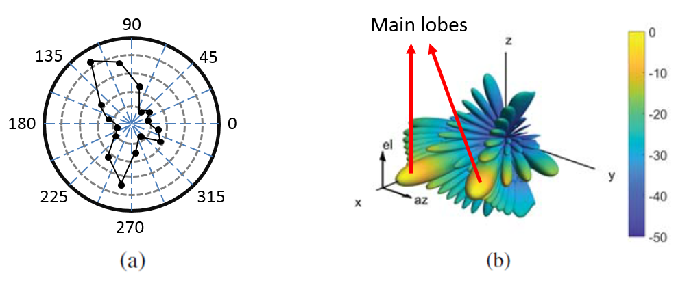
Figure 9: Exploiting multiple channel clusters. (a) Power profile for different beam directions, where the received power progressively increases with each outer circle, (b) illustration of a multi-lobe design.
SmartLink uses a logarithmic-time search scheme called MLBS for the discovery of multiple channel clusters in a directional mmWave system. MLBS is based on a binary decision tree (see Figure 10), which identifies the optimal sequence of beams to probe. It employs an adjustable signal detection threshold to minimize the misdetection of users, while also limiting false alarms. To generate an optimal multi-lobe pattern, SmartLink splits the antenna array into several sub-arrays. This splitting depends on the discovered channel clusters, their relative strengths, and their blockage probabilities.
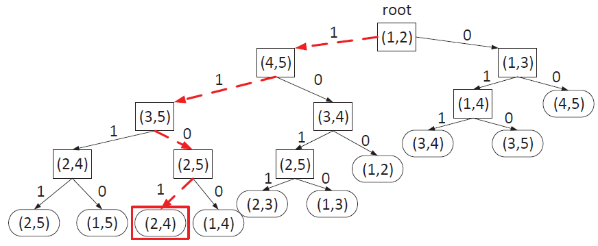
Figure 10: Example decision tree used in MLBS. During the execution of the search process, the traversed path is shown in red dashed lines and the discovered clusters are shown in the red box.
Extensive simulations were used to verify the efficiency of SmartLink in terms of reducing the search time and increasing the data rate. These simulations were driven by real mmWave channel traces (see Figure 11), obtained by utilizing phased-array antennas at 29 GHz. As shown in Figure 12, with a proper number of main lobes of the antenna pattern, SmartLink reduces the search latency by up to 65% compared to 802.11ad and by 88% compared to 5G NR beam scanning approaches. In addition, our results show that utilizing multiple clusters provides an efficient mechanism against blockages, and improves the average data rate by 10%, see Figure 12(b).
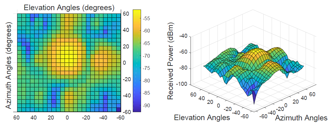
Figure 11: Received powers for different beam directions at 29 GHz operating frequency (hardware measurements).
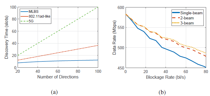
Figure 12: Performance of MLBS. (a) Comparison of cluster discovery times between MLBS, 5G and 802.11ad-like beam search approaches for discovering 2 clusters, (b) data rate vs. blockage rate when using 1, 2 or 3 simultaneous beams for transmission.
mmWave Channel Characterization
Efficient and reliable mmWave communications require knowledge of the channel state between the transmitter (Tx) and the receiver (Rx). Such information can be utilized to design robust waveforms and adapt these waveforms on the fly to account for channel fluctuations, pointing errors, and beam misalignment. Existing channel characterization studies of sub-6 GHz bands often target omnidirectional communications under rich scattering. Such assumptions are not applicable to mmWave RF frequencies. The clustered nature of mmWave channels and the use of electronically steerable antennas to create narrow beams have significant implications on channel characteristics, including Doppler spread, coherence time, delay spread, and coherence bandwidth.
In this research thrust, we focus on highly directional mmWave wireless systems under mobility. We provide both theoretical analyses, supported by detailed simulations (based on 3GPP models) and measurements, with the goal of assessing the impact of various system parameters on the channel attributes. For the antenna model, we consider electronically steerable planar antenna arrays at both ends of a mmWave link. Our objectives include the following:
- Provide theoretical analysis of channel coherence time and coherence bandwidth for both single- and multi-carrier mmWave systems
- Analyze the beam coherence time at mmWave frequencies
- Design optimal beam selection techniques at both the Tx and Rx so as to maximize the spectral efficiency, while considering the effect of beamforming on coherence time and coherence bandwidth
- Develop machine learning methods for real-time channel characterization and fast beam adaptation
- Conduct comprehensive simulations and experiments to validate our analytical results in LOS/NLOS scenarios
One sample of our studies is described here, where we investigate the effect of beamforming on the delay spread. Considering uniform planar arrays at both Tx and Rx, we derived closed-form expressions for the power delay profile, average delay spread, and RMS delay spread. Our theoretical results show that the antenna size, beamforming direction, and beam misalignment significantly affect the delay spread. A sample scenario is depicted in Figure 13, where both Tx and Rx perform beamforming, and multiple copies of the transmitted signal arrive at the Rx through various, spatially correlated paths. Depending on the Tx and Rx beam directions and beamwidth, the number of paths captured at the Rx varies, impacting the power delay profile, and thus the delay spread.
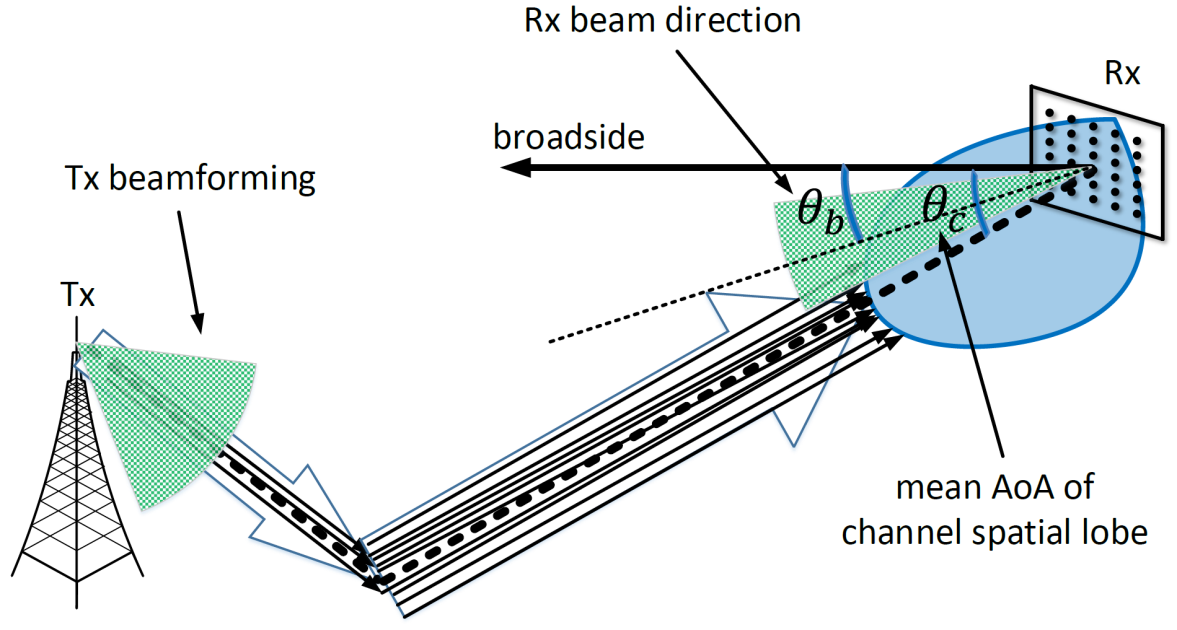
Figure 13: Tx signal reaches the Rx by propagating through multiple paths. The figure shows the Rx angular power distribution within a certain range of angles, called channel spatial lobe.
Using our delay spread analysis, we studied the the optimal selection of the Rx beamformer for a given Tx beamformer, aiming to maximize the spectral efficiency. The goal here is to find an Rx beam direction that results in low delay spread and that achieves high SNR. (Note that an increase in the delay spread results in an increase in inter-symbol interference (ISI), leading to poor system performance.) To minimize the effect of ISI, our beam selection method reflects both the instantaneous received signal power and the resulting delay spread.
To verify our analytical results, we conducted extensive simulations and experiments. In our simulations, we implemented the most recent 3GPP channel models for mmWave communications, incorporating uniform planar arrays with non-isotropic elements. In Figure 14(a), the effect of LOS direction between the Tx and the Rx is studied by comparing our Rx beam selection method with a benchmark scheme that chooses the Rx beam direction based on the highest instantaneous received power. An urban macro-cell scenario under LOS conditions is considered, using 46 dBm Tx power, 60 GHz operating frequency, 100 MHz bandwidth, and 100 meter Tx-Rx distance. A uniform planar array of half-wavelength spacing and non-isotropic antenna elements were implemented for different numbers of antennas (M). The results indicate that the proposed scheme always outperforms the benchmark, as it considers the effect of ISI due to delay spread. When M=16 and LOS direction is zero degree, the data rate is increased by 20% by employing our method. The performance gain increases with the increase in the LOS direction.
In the experiment setup, a 20 dBi gain horn antenna was used at the Tx side to transmit a continuous wave (CW) signal with 0 dBm power at 28 GHz frequency. At the Rx side, a 4x8 uniform planar array was used. As shown in Figure 14(b), our experimental results show that the proposed method increases the data rate over the benchmark method by up to 18%.
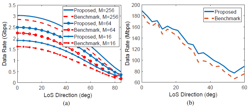
Figure 14: (a) Simulation results for data rate vs. LOS direction (deg) under various Rx antenna sizes when Tx power is 46 dBm, operating frequency is 60 GHz, bandwidth is 100 MHz, and Tx-Rx distance is 100 m. (b) Experimental results for data rate vs. LOS direction (deg) between Tx and Rx, separated at 3.5 meters.
The impacts of the Rx beam direction and beam misalignment on the RMS delay spread are shown in Figure 15 using simulations. Particularly, in Figure 15(a), we study by the effect of Rx beam direction for various Rx antenna sizes (M), when the Tx and Rx antenna planar arrays are facing each other. Figure 15(b) demonstrates the impact of beam misalignment on the delay spread for various LOS angles between the Tx and Rx antenna arrays.
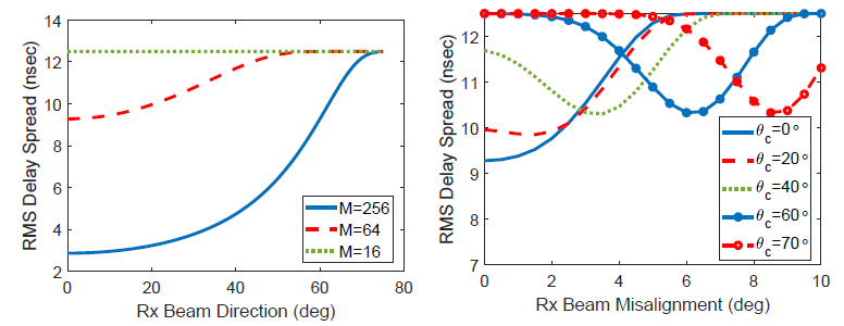
Figure 15: RMS delay spread (nsec) versus: (a) Rx beam direction, and (b) Rx beam misalignment.
Sharing and Dynamic Allocation of mmWave Spectrum
In its ruling, the FCC decided to adopt different spectrum policies for different mmWave bands. In particular, geographical area licensing was introduced as a means to provide licensees that enable localized services, allow targeted deployments based on market forces and customer demand, and facilitate access for both small and large wireless operators. To protect incumbent federal military operations in the 37 GHz band, a 600 MHz band (37-37.6 GHz) was made available for "coordinated coequal shared access" between federal and non-federal UEs. The same technical standards of the 57-64 GHz band were applied to the 64-71 GHz band, creating a total of 14 GHz ultra-wide band for unlicensed devices, including WLAN systems (e.g., WiGig), short-range devices for interactive motion sensing, and others.
The overarching goal of this project is to advance our understanding of how the unique aspects of the mmWave in terms of technology and spectrum policy can impact the interaction among operators and spectrum users, and how these impacts can be exploited to incentivize operators to compete and cooperate for efficient sharing of the mmWave bands. In particular, in the licensed bands, the geographical area licensing policy issues a single license to a specific area (see Figure 16). This may result in low spectrum utilization efficiency in areas that attract mutual interests from multiple operators such as many urban areas. For example, a cautious operator may not be willing to share its licensed bands if it does not receive detailed information about traffic, direction and location information of other nearby operators, even if such operators are unlikely to cause harmful interference. How to incentivize cooperation of operators to share/lease their spectrum without disclosing their private information is still an open problem. In the unlicensed bands, the FCC's spectrum policy tends to encourage both large and small operators to share the same spectrum with equal rights. This may result in a large number of devices sharing the same spectrum, increasing the chances that two or more of devices point to the same location from similar directions and causing unacceptable interference to each other. In addition, the traffic demands of different operators vary in time and location. How to exploit the temporal, spatial and directional diversities between operators to further improve the spectrum utilization efficiency of mmWave bands is a critical issue. In this project, we are developing a unified framework to model, analyze, and optimize spectrum sharing among operators in both licensed and unlicensed mmWave bands. This framework will serve as the basis for flexible and robust spectrum sharing in other mmWave bands.
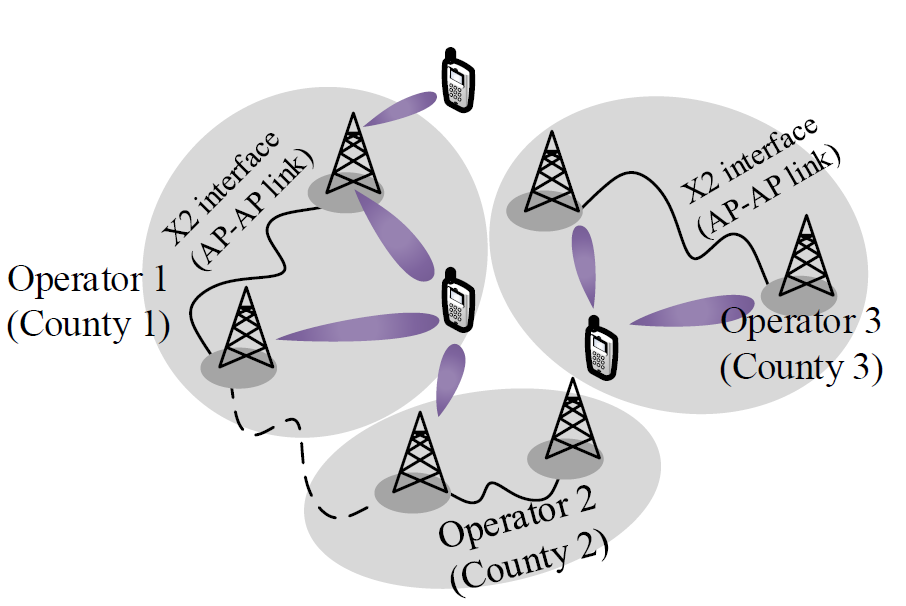
Figure 16: Illustration of geographical area licensing.